Part 1 of this blog post discussed some important considerations for custom mold designs for injection molding projects. Topics included the impact of resin selection and mold construction materials. Now, let’s consider how the resin is injected into the mold and the impact of the wall thickness of the part.
Mold Gate Types
The opening through which resin is injected while molds are clamped together is known as the gate.
The gate’s design, location, and type have important effects on the final part, including packing, gate vestige, dimensions, warping, and overall cosmetic appearance.
Two types of gates are used in injection molding: manually trimmed and automatically trimmed.
Manually trimmed gates require an operator to separate parts manually from the runners after each cycle. This type of gate would typically be selected for materials such as PVC that cannot be subjected to high shear rates, or the design requires simultaneous flow distribution across a wide front.
Automatically trimmed gates have a feature built into the mold that shears the part upon ejection. These types of gates are used to eliminate the need for manual shearing, which can help cut costs, maintain a consistent cycle time across all runs, and minimize part scarring.
Mold Gate Designs
Your mold’s gate design plays a major role in choosing which gate type to use. The size and shape of the component will dictate which gate designs are available for your application.
- Edge gates are located at the end of the part and are best suited for flat parts. They work well for parts with medium and thick sections. They can also be used on two-plate, multi-cavity tools. A scar will be visible at the parting line.
- Hot tip gates are usually located at the top of a part and are ideal for conical shapes where uniform flow is important. A small raised vestige is left at the gate location of the part.
- Valve gates produce no gate vestige, but instead leave a small witness mark on the part. They generate less shear than other gate types resulting in less warpage and better physical properties.
- Direct gates (also known as sprue gates) are used for single-cavity molds and provide symmetrical filling. A large scar is left behind at the point where trimmed. This is one of the easiest gates to design and maintain, helping to keep costs low.
- The sub gate is an automatically trimmed gate that requires ejector pins. Sub gates need not be located on the parting line, which allows for greater flexibility in gate location. The sub gate leaves a pin-sized scar.
Gate Location
A gate’s location on the mold is important because it is crucial to providing the best fill for the application. Gates should be placed at the heaviest cross-section, which allows for proper part packing while reducing voids and sinks. Gates should be located away from cores and pins to reduce obstructions in the path of the flow. If possible, place the gate in an area where stress from the injection will not detract from overall aesthetic requirements or functionality. The gate should also be located to shorten the flow path in order to prevent cosmetic flow markings. With the addition of multiple gates, optimum mold flow can be achieved, but weld lines, also known as knit lines can become an issue. A weld line is created where two flow fronts meet and are not able to meld together. This can have a weakening effect on the part.
Keep in mind that the mold’s gates can vary in both shape and size. This is usually determined by the size and shape of the part. Larger parts require larger gates. Smaller gates provide a better appearance, but they can take longer to mold or require higher pressure for a proper fill.
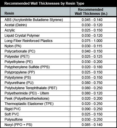
Wall Thickness
Wall thickness is among the most important features of your injection molded component. The part’s wall thickness can have a major impact on production quality, speed, and cost of the final parts.
Although there is no ideal wall thickness for injection molding, as a rule, minimizing wall thickness is usually the goal during design to reduce cost and weight. Parts with thinner walls require less material and less time to cool, both of which can greatly reduce cost. Minimizing wall thickness requires taking factors like structural requirements, the specific resin being used, and the part’s size and shape into account.

A constant wall thickness is key to molding high quality parts. Thicker sections take longer to cool than thinner sections. That means thin walls are already cool while the thicker walls are still cooling, which causes them to shrink around the thinner walls. That can cause the component to warp, crack, and twist. If different wall thicknesses are necessary, make the change in thickness gradually; overall differentiation should be no greater than 10 percent. There is a trade-off however. Thin walls will require higher injection pressures and tend to be less forgiving for stresses. An experienced mold designer can help you come up with design alternatives such as using cores and ribbing.
Other Mold Design Considerations
When designing custom molds for your parts, also consider issues like draft, sink marks, textures, and parting lines. The mold draft facilitates removal of the part from the mold. The degree of draft will vary with geometry and other part characteristics including surface texture requirements. In general, the more draft the better. Sink marks occur when the exterior walls cool faster than interior ones, creating warpage or unsightly marks or adding stress to the part. These marks most commonly occur at bosses, corners, and ribs.
Considerations to eliminate sink marks include reducing the thickness of an area by coring it out or making sure bosses and ribs are no more than 60% of the thickness of the nominal wall. Parts can also be molded with a texture in the mold.
Adding textures can provide functionality or improve cosmetic appearance while hiding imperfections such as sink marks and parting lines. Every molded part will have parting lines. Given that the parting line is the easiest place for venting, melted resin will always flow toward it. Consider your application when creating the parting line. A sharp edge at the parting line will it less visible while a safety edge radius is preferable for medical applications or toys.
Keeping these things in mind when designing your custom mold and discussing them with your designers and engineers will help to ensure you achieve the most economical solution for your injection molding process.
Learn More:
- Custom Mold Design – Part 1
- Structural Foam Molding Process Produces Lighter, Stronger Parts at a Lower Cost
- Custom Mold Manufacturing Capabilities
- Custom Structural Foam Molding
{{cta(’86c1e393-dd82-41b1-a2be-2914f7c7e0f4′)}}